
The core function of a network cable is to establish a physical transmission path for data among conductors, and data transmission itself is a continuous series of physical conversions. This physical pathway operates on three fundamental dimensions: data is first encoded into fluctuating voltage levels, these voltages propagate along the conductors in the form of electromagnetic waves, and signal attenuation inevitably occurs during propagation. The study of transmission principles revolves around precisely these three phenomena.
I. Signal Form: Voltage Waveforms

Data transmitted inside a network cable exists in the form of voltage waveforms. The transmitting terminal continuously switches between high and low output voltages at a fixed rate: a high voltage represents binary 1, and a low voltage represents binary 0. The receiving terminal samples the incoming waveform at the identical clock rate and decodes binary bits by measuring the voltage value at each sampling instant.
The number of voltage state transitions per second at the transmitter is defined as the baud rate, measured in Baud. The amount of information carried per voltage state depends on the number of distinct voltage levels. If only two levels (high and low) are differentiated, each Baud conveys 1 bit, making the bit rate equal to the baud rate. By contrast, when voltage is divided into multiple tiers—for instance, five discrete levels—approximately 2.3 bits can be encoded per Baud, drastically boosting the data throughput at the same baud rate. This is the core logic of multi-level modulation.
Gigabit Ethernet transmits PAM-5 five-level signals at 125 MBaud on each twisted pair, delivering 250 Mbps per pair and aggregating to a total throughput of 1 Gbps across four twisted pairs. 10-Gigabit Ethernet upgrades to PAM-16 modulation with 16 voltage levels. Combined with forward error correction (FEC), each symbol carries 3.125 effective bits, yielding an overall bandwidth of roughly 10 Gbps—all achieved within the same copper cable.
II. Propagation Mechanism: Electromagnetic Waves

An electrical signal is an electromagnetic wave generated by the mutual induction of alternating electric and magnetic fields. High-frequency signals propagate as electromagnetic waves along the conductor surface and the surrounding insulating dielectric material. Notably, the drift velocity of free electrons is far slower than the propagation speed of the electromagnetic wave itself.
Electromagnetic waves travel through copper twisted pairs at approximately two-thirds of the speed of light in a vacuum, equivalent to around 2×10⁸ m/s, translating to a propagation delay of roughly 5 nanoseconds per meter. This physical delay governs the one-way transit time from the source to the receiver: a 100-meter link incurs a single-pass delay of about 500 nanoseconds.
Wave propagation along the cable is governed by the distributed parameters of the transmission line. Every infinitesimal segment of the wire possesses series inductance (L) and shunt capacitance (C). Inductance resists rapid fluctuations in current, while capacitance accumulates electric charge. Together, they determine the characteristic impedance of the transmission line, expressed as \(Z_0 \approx \sqrt{L/C}\), which refers to the instantaneous ratio of voltage to current at any point along the traveling electromagnetic wave. Standard Ethernet twisted pairs are engineered for a characteristic impedance of 100 ohms. Uniform impedance throughout the entire link ensures complete transfer of electromagnetic energy from the transmitter to the receiver without reflection losses.
III. Propagation Limitation: Attenuation
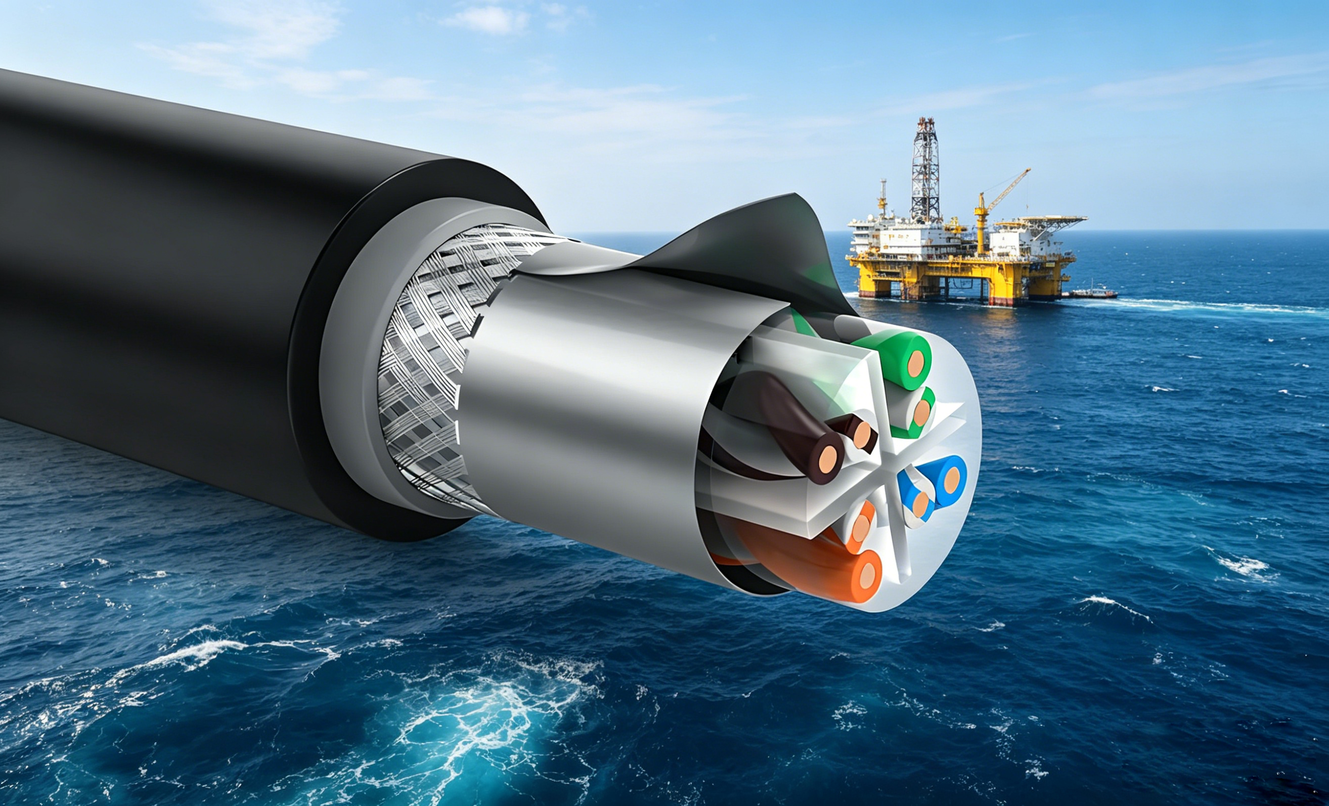
As signals traverse copper conductors, their amplitude gradually diminishes with increasing distance, a phenomenon known as attenuation. Two primary physical mechanisms contribute to this loss:
- Conductor resistive loss: Copper is not a perfect zero-resistance conductor, and current flow dissipates energy as Joule heat. At higher frequencies, the skin effect confines current to a thin outer layer of the conductor, reducing the effective conductive cross-sectional area and raising equivalent resistance. Conductor loss scales proportionally with the square root of frequency.
- Dielectric loss in insulation: The plastic insulation undergoes repeated polarization under high-frequency alternating electric fields, converting part of the electromagnetic energy into thermal waste. This dielectric loss increases linearly with frequency.
The superposition of these two losses results in a universal rule: higher signal frequencies incur more severe attenuation and shorter maximum transmission distances. This physical constraint directly dictates the relationship between cable category and reach. For example, 10-Gigabit Ethernet operates over a 500 MHz frequency band, requiring Category 6A (Cat6a) cabling to support the full 100-meter standard link length. Category 6 (Cat6) cable only has a 250 MHz bandwidth ceiling; limited by attenuation and alien crosstalk, 10 Gbps signals typically only reliably travel 37 to 55 meters over Cat6.
Conclusion
The three mechanisms address distinct layers of transmission performance: voltage waveforms determine data rate, electromagnetic wave velocity governs propagation latency, and the frequency-dependent attenuation curve defines cable grading and maximum transmission distance. These factors are intrinsically interconnected: higher frequencies enable faster voltage toggling yet exacerbate attenuation and shorten feasible cable runs. The transmission performance of a network cable ultimately represents a carefully engineered balance of these three physical properties within copper conductors.
Post time: Aug-12-2026