
In shipbuilding and ocean engineering, optical cables are commonly classified into three categories by the fiber protection method: single loose tube, multi loose tube and tight-buffered fiber. Although the three structures appear similar, they differ greatly in performance and applicable scenarios. Understanding their distinctions is critical for offshore optical cable selection.
I. “Loose” vs “Tight”: Two Fiber Protection Mechanisms
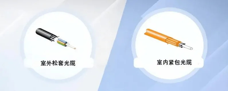
The core component of an optical cable is the glass optical fiber. Brittle and stress-sensitive, the fiber must be protected by buffer structures. There are two mainstream buffer protection designs: loose tube and tight buffer.
- Loose Tube: Optical fibers are housed inside a plastic tube filled with thixotropic grease. Fibers float freely within the tube. During bending or tension, mechanical stress is borne mainly by the cable strength members. The tube provides sliding clearance so the fiber itself barely bears any load. Loose tube designs fall into two types based on this principle: single loose tube (single central tube) and multi loose tube (stranded tubes).
- Tight Buffered: A buffer layer is extruded directly onto the fiber, forming a tight bond with no gaps or grease. The buffer layer and fiber are integrated. Bending or tensile stress transfers directly to the optical fiber.
In short: a loose tube provides extra accommodation space for fibers, while tight buffer fuses the fiber and buffer layer into one unit.
II. Single Loose Tube (Central Tube Design): Simplest Structure
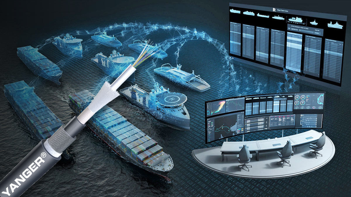
In a single loose tube (central bundle tube) cable, all optical fibers are contained within one central tube at the cable core, protected by grease. Strength members such as steel wires are arranged longitudinally outside the tube, followed sequentially by water-blocking layers, armoring and outer sheath.
Advantages
- Simplest construction; smallest outer diameter, lightest weight and lowest cost among the three for a given fiber count and sheath rating
- Fibers concentrated in one tube, delivering good bending performance
Limitations
- Limited fiber capacity (typically ≤12 cores); higher fiber counts will degrade attenuation performance
- Moderate resistance to lateral pressure, low mechanical redundancy
Typical applications: Short-distance transmission in shallow water, onboard main routes, weight-sensitive cabling inside engine rooms.
III. Multi Loose Tube (Layer-Stranded Design): Primary Offshore Cable Structure

Single loose tube cables are limited in fiber count and lateral pressure resistance. For higher fiber counts and harsher installation environments, multi loose tube designs are adopted. Multiple loose tubes (2–12 fibers per tube) are helically stranded around a central strength member (steel wire or FRP glass fiber rod). The assembly is wrapped with water-blocking layers, armoring and outer sheath in sequence.
Advantages
- Large fiber capacity: available in 12, 24, 48 fibers and up to hundreds of fibers
- High mechanical redundancy: load shared by multiple tubes; superior tensile and lateral pressure resistance compared with single loose tube. Fibers are protected by multi-layer barriers including grease, tubes and armoring, isolating seawater, vibration and temperature fluctuations.
Limitations
- Largest outer diameter and weight among the three, unsuitable for space- or weight-restricted locations
- Highest cost due to complex stranding process and greater material consumption
- Labor-intensive splicing: each tube must be stripped and grease cleaned individually, leading to longer fusion splicing time
Typical applications: Ship backbone communications, inter-platform submarine cables, umbilical cables — the preferred choice for installations requiring long-term maintenance-free operation.
IV. Tight-Buffered Fiber: First Choice for Equipment Interconnection and Sensors

Unlike the above two designs relying on loose tubes and grease, tight-buffered cables adopt a different approach: the buffer layer tightly encases the fiber, featuring a small outer diameter and enabling single-fiber handling.
Advantages
- Easy splicing: fusion splicing can be performed after stripping the buffer layer without grease cleaning, ideal for cabinet and equipment-side connections
- Small minimum bend radius and good flexibility
Limitations
- Stress transfers directly to the fiber, resulting in poor tensile and lateral pressure performance
- No grease for water blocking; waterproofing and moisture resistance rely solely on the outer sheath, not suitable for long-distance underwater deployment
Typical applications: Cabinet jumpers, sensor pigtails, short-range interconnections between equipment.
Comparison Table for Selection of the Three Structures
表格
| Parameter | Single Loose Tube (Central Bundle Tube) | Multi Loose Tube (Layer-Stranded) | Tight-Buffered |
|---|---|---|---|
| Fiber Capacity | Small (≤12) | Large (12 up to hundreds) | Small (1–12) |
| Tensile / Lateral Pressure Resistance | Medium | Strong | Weak |
| Splicing Ease | Medium | Medium | High (grease-free) |
| Outer Diameter / Cost | Small / Low | Large / Medium | Small / Medium |
| Offshore Suitability | Short-distance, lightweight deployment | Mainstream structure | Equipment-side, sensor use |
V. Summary

As shown above, layer-stranded cables lead in core metrics including fiber capacity, mechanical strength and water blocking. Given harsh offshore conditions (heavy salt spray, high humidity, wide temperature variation and mechanical vibration), multi loose tube (layer-stranded) cables are the mainstream option for offshore optical cable selection. The other two types each have their suitable application niches. Selection can be comprehensively determined by the following criteria:
- Priority on waterproofing: loose tube cables with integrated grease and water-blocking structures are naturally advantageous
- Reliability over convenience: multi loose tube cables offer multi-layer fiber protection for long-term maintenance-free service after installation
- Tight-buffered cables are only for indoor equipment areas with no water exposure and low mechanical load, where splicing efficiency becomes the key consideration
Post time: Sep-09-2026