As the global shipping industry moves toward intelligence, the importance of marine fieldbus cables has become increasingly prominent. These cables not only carry data communication tasks among various sensors, actuators, and controllers within a vessel but also serve as the critical infrastructure for achieving ship automation, remote monitoring, fault diagnosis, and energy efficiency optimization. Faced with harsh offshore conditions such as high salt spray, high humidity, extreme temperature variations, and complex electromagnetic environments, marine fieldbus cables utilize specialized material selection and structural design to exhibit excellent corrosion resistance, flame retardancy, low smoke and halogen-free properties, and anti-electromagnetic interference capabilities, ensuring long-term stable operation in demanding marine environments.
This article provides a detailed introduction to the structure of marine fieldbus cables. We hope this article will help readers gain a better understanding of the structural, design, and material aspects of marine fieldbus cables.
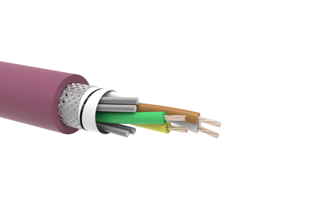
1. Basic Structure Introduction

1.1 Conductor
The conductor material for marine fieldbus cables is typically stranded tinned copper. Stranded conductors ensure the electrical performance and mechanical service life of the fieldbus cable, while also facilitating installation. Compared to bare copper conductors, tinned copper conductors offer superior resistance to salt spray corrosion. The use of stranded tinned copper conductors simultaneously addresses challenges such as high-frequency attenuation, bending fatigue, salt spray corrosion, low-temperature brittleness, and space constraints during installation, making it highly suitable for marine fieldbus cables.
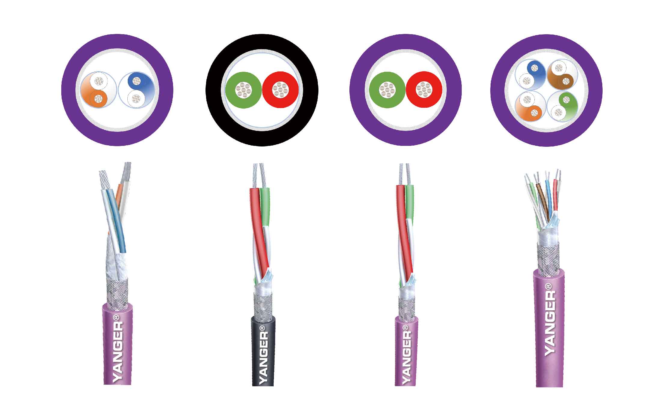
Different types of marine fieldbus cables have varying conductor configurations. For example, CANBUS and RS485 cables typically consist of 1, 2, or 4 pairs of twisted wires; Profibus cables feature two cores; and Profinet cables have four cores. Correspondingly, the characteristic impedance values differ: CANBUS and RS485 are 120 Ω, Profibus is 150 Ω, and Profinet is 100 Ω.
1.2 Insulation
The insulation material for marine fieldbus cables is foamed polyethylene (Foam-PE). The use of foamed polyethylene insulation effectively reduces the dielectric constant, thereby minimizing signal attenuation, while also providing longitudinal water-blocking properties. Additionally, foamed polyethylene helps reduce the overall weight of the cable, contributing to lower vessel weight.
1.3 Shielding
The shielding layer of marine fieldbus cables is similar to that of marine network cables, typically consisting of an aluminum-polyester composite tape combined with a tinned copper wire braid. The shielding layer functions to block electromagnetic interference, ensuring stable signal transmission. The aluminum foil generally has a thickness of no less than 0.012 mm and provides 100% coverage. The tinned copper wire braid typically uses 0.12 mm diameter monofilaments with a braid coverage of no less than 60%. In most cases, marine fieldbus cables employ a dual shielding structure combining an aluminum-polyester composite tape and a tinned copper wire braid, forming a composite shield that enhances the cable’s shielding performance to 70–90 dB at 30 MHz. Typically, a solid or stranded tinned copper drain wire is also included to provide an additional grounding path.
1.4 Sheath
The sheath serves to protect the cable from external environmental hazards. As the first line of defense, the sheath material for marine fieldbus cables must possess properties such as salt spray corrosion resistance, abrasion resistance, and flame retardancy to ensure reliability and safety in harsh environments.
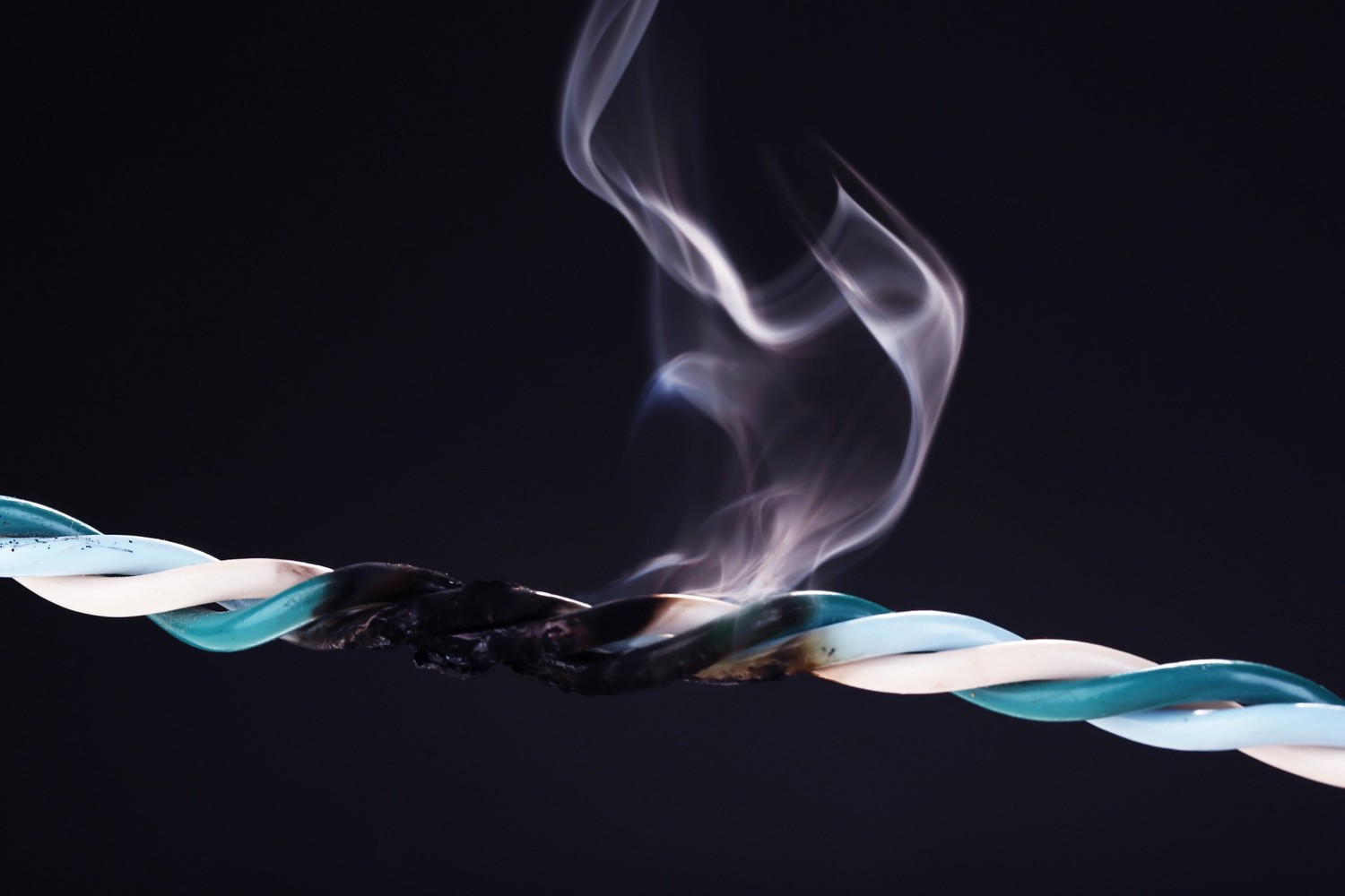
To enhance the safety of shipboard communication systems, marine fieldbus cable sheaths are typically made from low smoke zero halogen flame-retardant polyolefin (LSZH-SHF1) material. This material does not emit toxic fumes when burned, complying with the stringent requirements of the International Maritime Organization (IMO) and classification societies (such as DNV, ABS, CCS, BV, LR, etc.), while also meeting the IEC 60332-1 standard for single cable flame retardancy, IEC 60332-3-22 for bundled cable flame retardancy, as well as the low smoke and halogen-free requirements of IEC 60754-1/2 and IEC 61034-1/2. This not only reduces the hazards to crew members in the event of a fire but also minimizes environmental pollution.
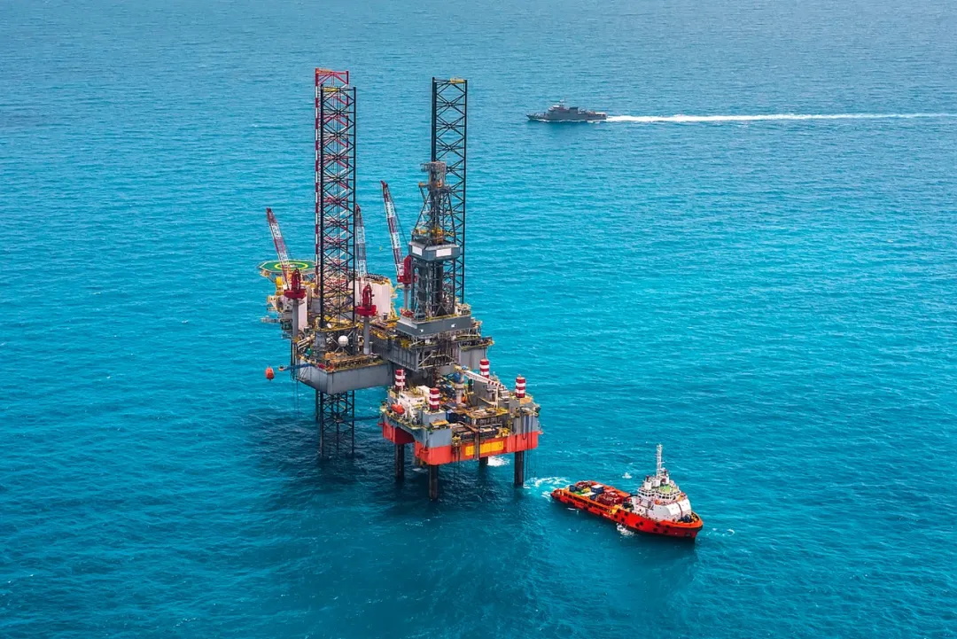
For applications such as offshore platforms, where cables may also need to withstand exposure to oil and drilling mud, the sheath is made from LSZH-SHF2 material with enhanced oil resistance, or LSZH-SHF2-MUD material with enhanced mud resistance.
1.5 Special Structures
In general, the conductor + insulation + shielding + sheath configuration is sufficient for most marine applications. For applications with higher requirements, the fieldbus cable structure may be modified accordingly to meet specific needs.
For example, in applications requiring additional mechanical protection, an armor layer may be added to the structure, along with an additional outer sheath to form a double-sheath armored construction. The armor layer is typically a galvanized steel wire braid, which effectively enhances the cable’s mechanical properties and prevents damage in harsh environments.
When cables are required to maintain functionality during a fire, a mica tape wrapping layer is added over the insulation to meet the fire resistance standards specified in IEC 60331 and the requirements for safe return to port.
2. Conclusion

The structural design and material selection of marine fieldbus cables are key to their ability to transmit signals stably and reliably in harsh marine environments. From tinned copper conductors and foamed polyethylene insulation to low smoke zero halogen flame-retardant sheaths, each design element has undergone numerous iterations and optimizations. This excellent structural design ensures that marine fieldbus cables can operate continuously and stably in the challenging marine environment where engine room heat, salt spray corrosion, and strong electromagnetic interference coexist.
Post time: Apr-01-2026