In today’s highly digitized world, the Internet has become an indispensable part of our daily life and work. Behind this, as a bridge connecting devices and networks, the transmission performance of network cables is crucial.
The transmission performance of Ethernet cables is directly related to the stability and speed of network connections. Whether it’s home networks or enterprise networks, we all expect to receive high-speed and stable data transmission services. This article will preliminarily explore the factors that affect the transmission rate of network cables and the general methods of network cable speed measurement.
1. The main factors affecting the transmission performance of network cables
Cable material: Cable material is a key factor affecting the transmission performance of network cables. High quality cables typically use pure copper or higher quality wire cores to ensure stable signal transmission.
Wire gauge (wire diameter): The wire gauge determines the electrical performance and transmission distance of the network cable. A thicker wire diameter can provide better signal transmission quality and longer transmission distance.
Shielding method: Shielding network cables can reduce the impact of electromagnetic interference (EMI) on signal transmission and improve the stability of data transmission. Common shielding methods include single shielding and double shielding.
Connection quality: The quality of connecting components such as crystal heads, modules, and distribution frames, as well as the crimping process between cables and connecting components, can all affect the actual transmission performance of network cables.

2. Knowledge related to network cable data transmission
In the process of network cable speed measurement, the following parameters are mainly tested: wiring diagram, length, information transmission rate, attenuation, distance, near-end crosstalk, etc. Below is an introduction to some basic parameters related to network cable transmission.
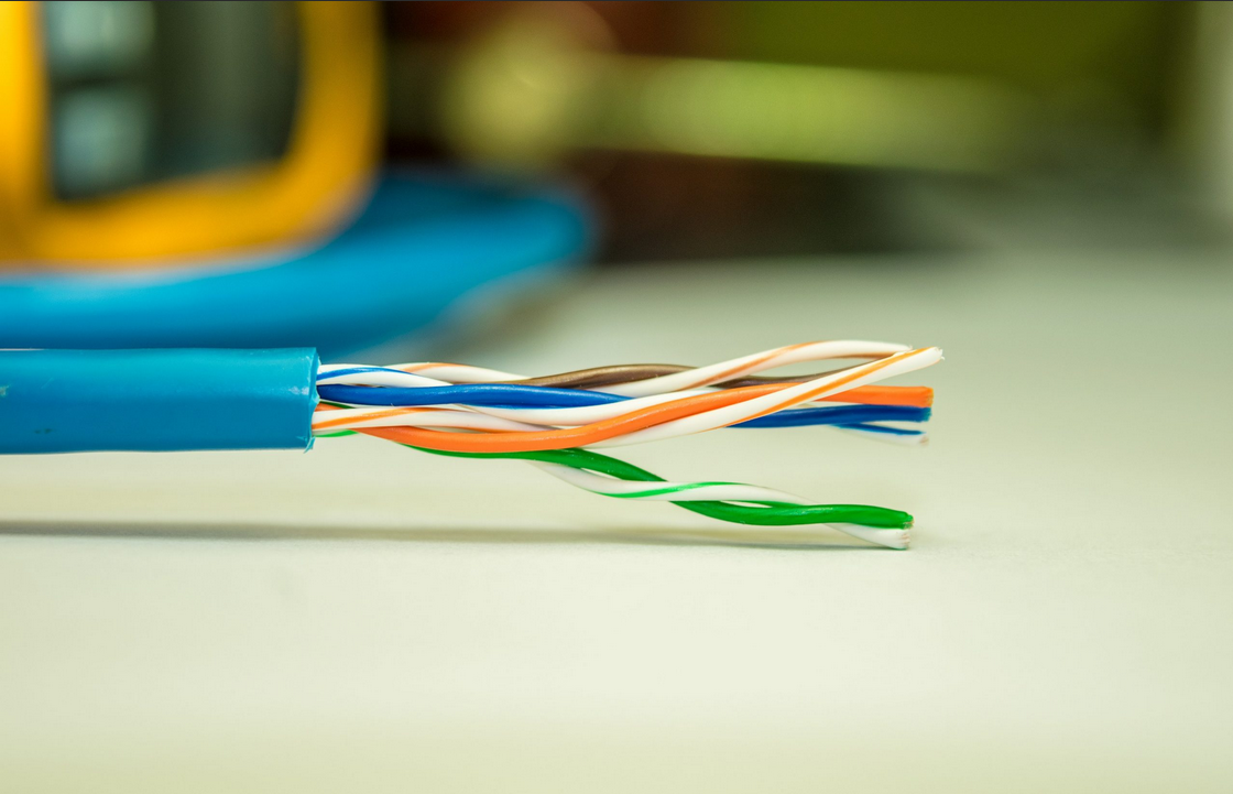
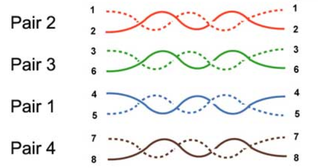
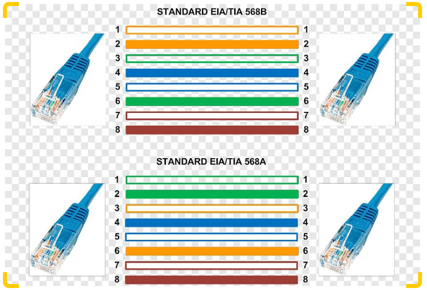
Wire Map
The wiring diagram is used to verify whether the eight core wires at the end of each cable are actually connected correctly to the wiring terminals, and to check the installation connectivity. There are two unified standard wiring methods for network cable crystal heads internationally: TIA/EIA 568A and TIA/EIA 568B. The TIA/EIA 568A standard is wired in order of (green white, green, orange white, blue, blue white, orange, brown white, brown), while the TIA/EIA 568B standard is wired in order of (orange white, orange, green white, blue, blue white, green, brown white, brown). Both ends of the network cable are wired according to the T568B standard, which is called a straight line. If one end of the network cable is wired according to the T568A standard, and the other end is wired according to the T568B standard, it is called a crossover line. When wiring on site, the connection method of the crystal head of the network cable should comply with the above two standards.
Line length
During network cable transmission, the maximum physical length of the basic link is 94 meters, and the maximum length of the channel is 100 meters. The length of the basic link and channel can be determined by measuring the length of the cable, or derived from the electrical length measurement of each pair of core wires. When the length of the link exceeds the above value, the transmission performance of the network cable will be significantly degraded.
Attenuation
Attenuation is a measure of the transmission loss of signal energy along a basic link or channel, which depends on the parameters of twisted pair resistance, distributed capacitance, distributed inductance, and signal frequency. The attenuation amount will increase with the increase of frequency and cable length, expressed in dB. The larger the attenuation value, the greater the loss of the transmitted signal.
Near end crosstalk loss (NEXT)
Near end crosstalk refers to the electromagnetic interference signal between the transmitting pair and other pairs on the same side in a twisted pair cable link. The NEXT value is a measure of this degree of coupling, which has a negative impact on signal reception. The unit of NEXT value is dB, defined as the ratio of the transmitted signal power that causes crosstalk to the crosstalk. The larger the NEXT, the lower the crosstalk, and the better the link performance. The cross skeleton or pair shielding structure in the network cable can effectively reduce crosstalk.
DC loop resistance
Any wire has resistance, and the DC loop resistance refers to the sum of the resistances of a pair of twisted pair wires. The DC loop resistor will convert a portion of the transmitted signal into heat, reducing transmission performance. The better the material used for the cable conductor, the lower the DC loop resistance, and the better the transmission performance of the network cable. According to the ISO/IEC 11801 standard, the DC resistance of twisted pair cables shall not exceed 19.2 ohms. The difference in DC resistance between each pair of twisted pairs should be less than 0.1, otherwise it indicates poor contact and the connection points must be checked.
Impedance
Characteristic impedance is a parameter that measures the main characteristics of the transmission channel composed of cables and related connectors. Generally speaking, the characteristic impedance of twisted pair cables is a constant, and the commonly used characteristic impedance of network cables is generally 100 Ω.
Attenuation to Near End Crosstalk Ratio (ACR)
The attenuation to near-end crosstalk ratio is the difference between the near-end crosstalk value and attenuation of a twisted pair cable. It represents the relative magnitude of signal strength and the noise intensity generated by crosstalk, expressed in dB. It is not an independent measurement value, but a calculation result of attenuation and near-end crosstalk (NXET Attenuation), with larger values being better.
Integrated Near End Crosstalk (Power Sun NEXT, PSNT)
Using multiple pairs of twisted pair cables to transmit and receive information in a single cable can increase crosstalk between a pair of wires in the cable. Integrated near-end crosstalk is the sum of the near-end crosstalk generated by all the tested pairs in a twisted pair cable. The larger the integrated near-end crosstalk, the greater the transmission signal loss.
Equivalent Level FEXT (ELFEXT)
A pair of lines sends a signal from the near end, while other pairs receive crosstalk signals. The crosstalk value attenuated by the line is measured at the far end of the link, which is called Far End Crosstalk (FEXT).
Propagation delay
Transmission delay refers to the delay time of a signal from the beginning to the end of a link. Due to the significant speed difference in parallel transmission of electronic signals on twisted pair cables, it can affect the integrity of the signal and cause errors. Therefore, the lower the transmission delay, the better. The transmission delay of the network cable should be less than 56ns/m.
Return Loss (RL)
Return loss is used to measure the impedance consistency of transmission channel characteristics. The characteristic impedance of the transmission channel varies with the frequency of the signal. If the impedance of the cables and related connectors used in the transmission channel does not match and causes impedance changes, the transmitted signal at the terminal will be reflected back, and a portion of the energy reflected to the transmitting end will form noise, leading to signal distortion and affecting the transmission performance of the comprehensive cabling system. The larger the absolute value of return loss, the better.
3. Common methods for measuring network cable speed
The commonly used testing standards currently include TSB-67, EIA/TIA-568A, and other standards developed by the American National Standards Association (EIA/TIA). TSB-67 includes specifications for cables and connecting hardware in UTP cabling defined by the EIA/TIA-568 standard. With the development and promotion of standards for Class 5 and Class 6 systems, the current EIA568 and TSB-67 standards have provided testing standards for Class 5 and Class 6 systems.
TSB-67 defines two standard testing models: Basic Link and Channel. The basic link is used to test the fixed link part in the comprehensive cabling system. Due to the fact that comprehensive cabling contractors are usually only responsible for the installation of this part of the link, the basic link is also known as the contractor link. It includes a horizontal wiring of up to 90m in length, with one connection point at each end and two 2m long jumper wires for testing.
Engineering acceptance testing generally chooses basic link testing. From the user’s perspective, the link used for high-speed network transmission or other communication transmission should not only include the basic link part, but also the user cable used to connect devices, so they hope to receive a channel test report. In the testing of integrated cabling engineering, commonly used testing instruments include the Fluke DSP-100 tester and the Fluke DSP-4000 series tester. The Fluke DSP-100 tester can meet the testing requirements of Class 5 cable systems. The Fluke DSP-4000 series tester has powerful functions and can meet the testing of Category 5, Super Category 5, and Category 6 cable systems. Below we will introduce the usage of the Fluke DSP-100 tester.
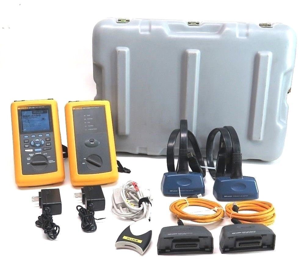
Connect the host and remote end of the Fluke DSP-100 tester to both ends of the tested link, respectively;
Turn the tester knob to SETUP;
Select test parameters based on the screen display, and the selected parameters will be automatically saved to the tester until the next modification;
Turn the rotary knob to AUTOTEST, press the TEST button, and the tester will automatically complete all tests;
Press the SAVE key, enter the tested link number, and store the result;
If a certain indicator is found to have failed during the test, turn the knob to Single TEST and perform the corresponding fault diagnosis test according to the Chinese quick reference table;
Troubleshooting and retesting until all indicators pass;
After testing all information points, connect the tester to the PC, import test data through the randomly provided management software, generate test reports, and print test results.
Finally, use Fluke Link Ware software to generate corresponding test reports, which will clearly provide the test results for each tested link. If the testing of the link is qualified, a conclusion of “PASS” is given, and the test results of each tested link in the test report are statistically analyzed to determine the compliance rate of the entire project.
Post time: Jan-17-2024